- +86-13526935931
- gwdlthermo@gwdl.com
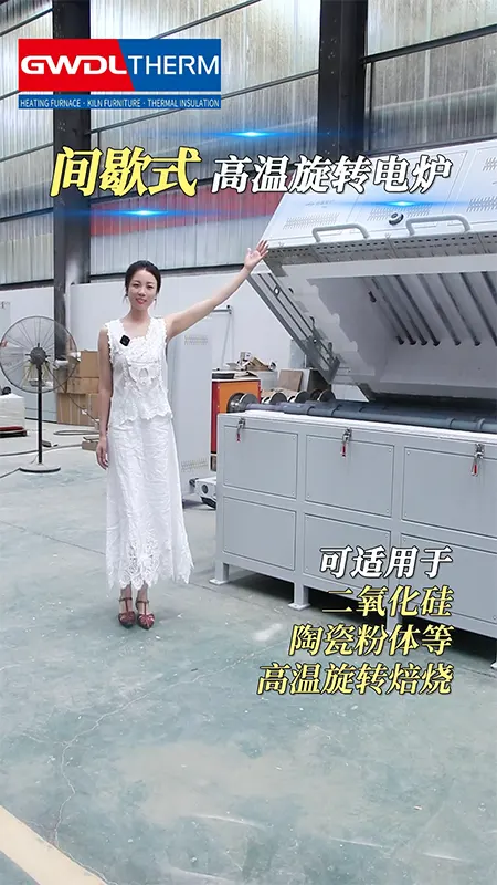
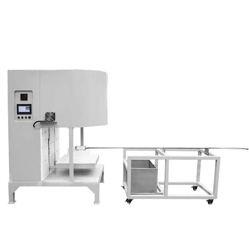
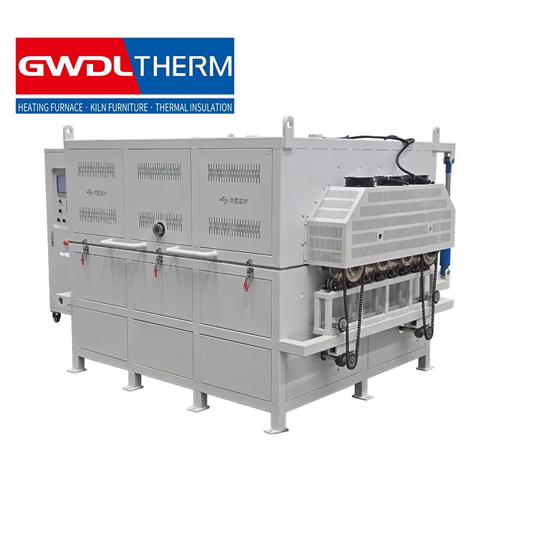
The intermittent rotary furnace is designed for batch thermal processing, providing uniform heating through controlled rotation for consistent treatment results.
Equipment Composition | Basic requirements |
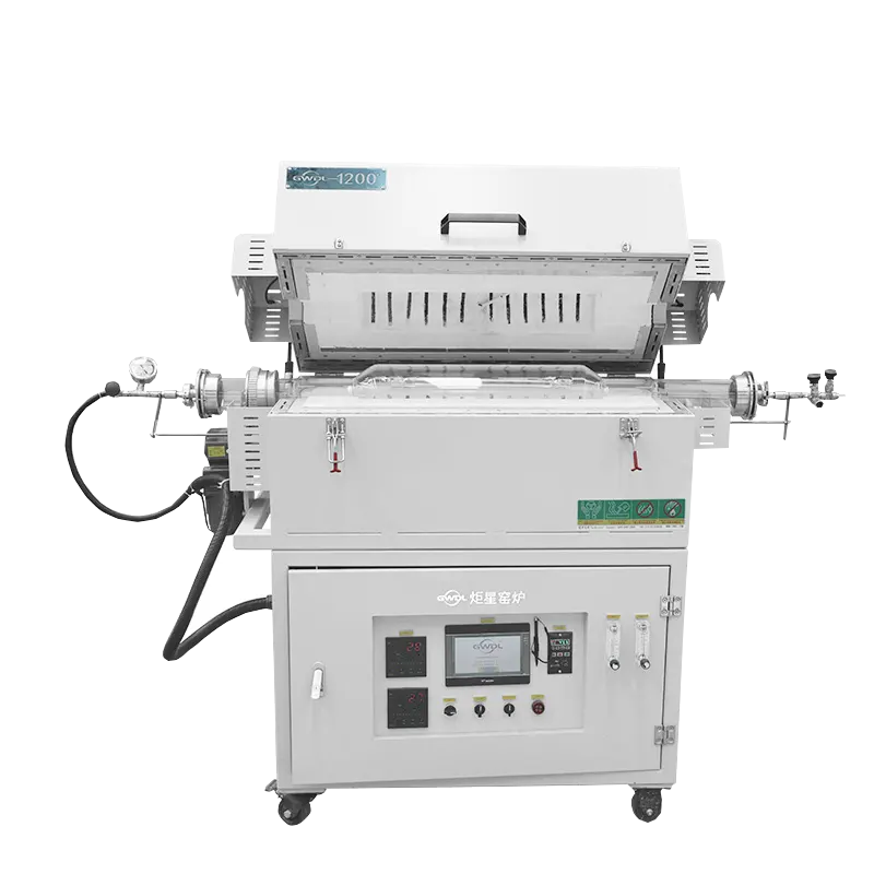
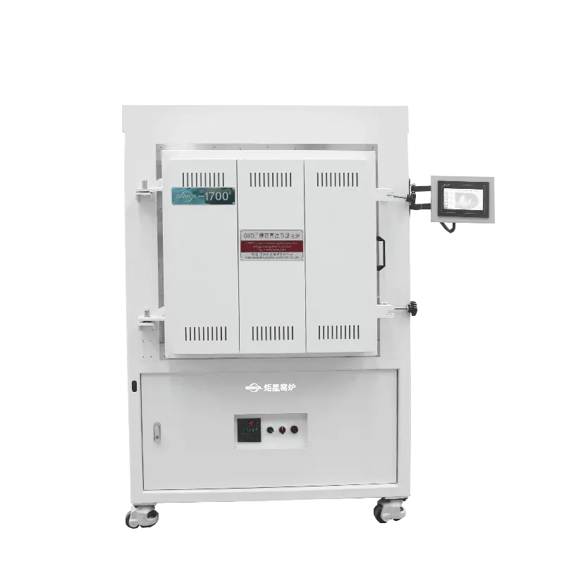
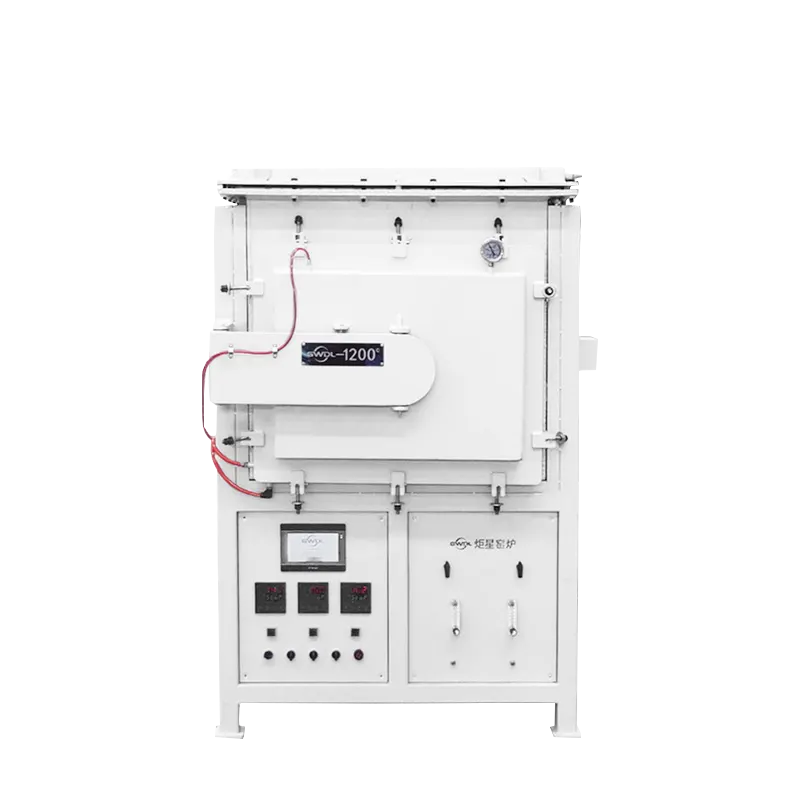
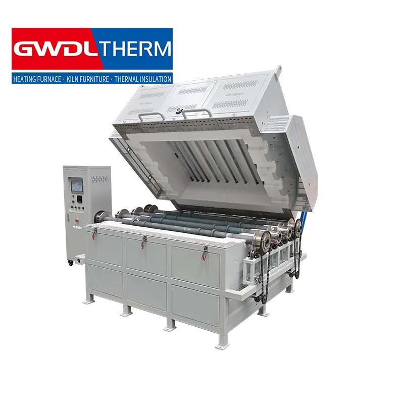
Furnace body structure | 1. The furnace shell has good temperature resistance and will not deform due to high temperature during long-term use. It is easy to clean, has a reasonable and beautiful color matching, and the paint does not bubble or run. 2. The transmission components are fully protected to avoid safety risks, and the electrical protection is complete; 3. The furnace shell structure is reasonable to avoid long-term overheating of local parts of the equipment (electrical components, hinges, clips, etc.) and affect its service life; 4. The opening of the furnace door should take into account the ease of operation to avoid inconvenience during high-temperature material handling, which could lead to safety issues such as high-temperature burns. If it is designed as a lifting type, the lifting height of the upper part of the furnace body should be greater than 1000mm . If it is another structural form, the opening angle of the furnace door should facilitate the insertion and removal of the quartz tube. In addition, the sealing performance should be improved as much as possible to prevent uneven temperature field. 5. Install 1-2 observation mirrors on the furnace body to observe the rotation of the quartz tube inside; 6. Within the operating temperature range, the surface temperature of the furnace shell during heating, heat preservation, and cooling processes should be ≤45℃ ; |
Furnace structure | 1. The furnace lining is made of vacuum-formed high-purity alumina lightweight material. The parts that are prone to collision when handling materials (furnace opening and furnace bottom) are made of lightweight hollow spherical alumina plates. It has high operating temperature, low heat storage, resistance to rapid heating and cooling, no cracking, no slag shedding, and good heat preservation performance. 2. Three layers of insulation are used: aluminum silicate fiberboard, alumina fiberboard, and alumina (polycrystalline) fiberboard. 3. Four to six silicon carbide rollers are inserted inside the furnace ; 4. The thickness of the insulation material should be carefully considered to avoid heat leakage problems; |
Furnace tube and roller structure | 1. The furnace tube is a quartz tube with a cap; see the drawings for dimensions. 2. The rollers are made of silicon carbide, with retaining rings welded to both sides or with a variable diameter, to fix the quartz tube and prevent it from moving left and right in the rotating quartz tube. See the drawings for the dimensions. The silicon carbide rollers need to be purchased and assembled by the equipment supplier. It is best to make two rollers with adjustable spacing to accommodate changes in the diameter of the quartz tube later . 3. Inside the quartz tube, there are turning plates welded at every 90° , with staggered welding, which can satisfy the powder turning effect and prevent the powder from sticking together and clumping; |
Rotary transmission structure | 1. The furnace body is equipped with a rotary transmission structure on both sides. The transmission mechanism is mainly based on friction transmission. After the silicon carbide rollers are subjected to force, they drive the internal quartz tubes to rotate. The transmission method must ensure that the radial force on the silicon carbide rollers is small to avoid cracking due to radial force, which would affect the service life . 2. The motor is equipped with a variable frequency motor, which is adjustable from 1-5 r/min and can be set to rotate in both forward and reverse directions; 3. Two sets of rotating mechanisms are designed to operate independently, with each transmission running synchronously on both sides, simultaneously driving the silicon carbide tubes. |
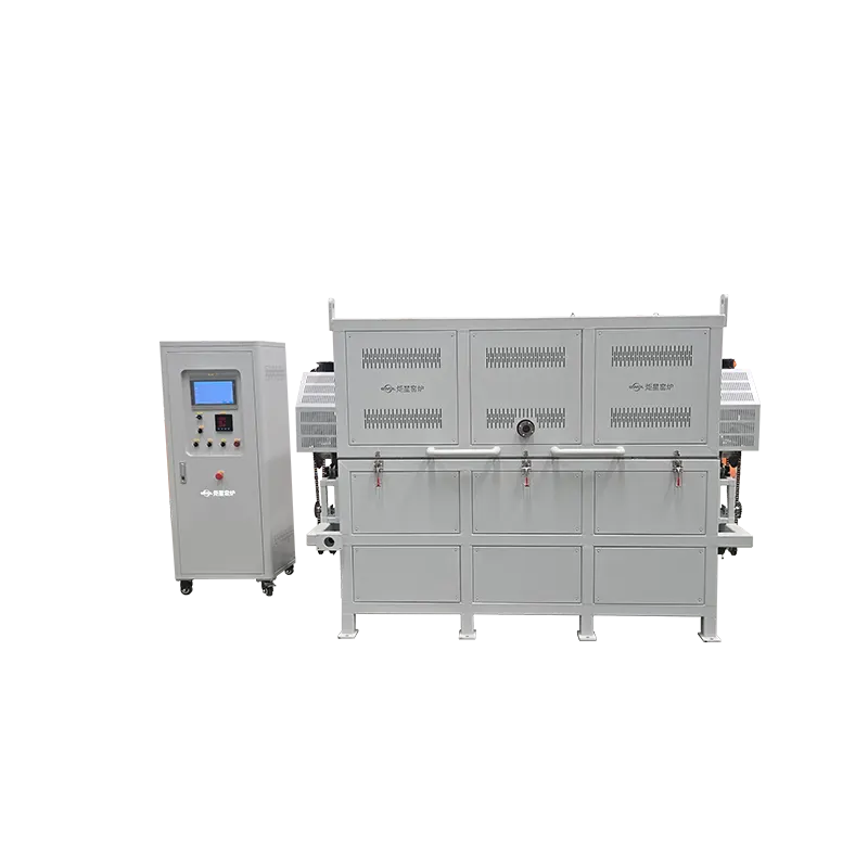
control system | 1. Temperature control processes can be saved in 5 or more steps, each containing 30 or more temperature settings, and can be edited online; 2. The temperature control system has functions such as continuous PID adjustment, thermocouple failure alarm, over-temperature alarm, real-time power display of equipment, and temperature compensation setting. It monitors the temperature in real time, records temperature curves, and exports historical data. 3. The control panel can be either touchscreen or keyboard and mouse-based; 4. Set automatic power consumption calculation to automatically calculate the power consumption for each furnace cycle; 5. Equipped with an emergency stop button; |
Heating and temperature control system | 1. Meets the operating temperature range of 1200~1400℃ , with an intermittent process cycle: room temperature heating → constant temperature for 2~8 hours → cooling down to room temperature. 2. The heating rate is freely adjustable, with an adjustment range of: fastest heating rate of 10 degrees per minute and slowest heating rate of 1 degree per hour ( 1 degree /h ). 3. Three or more temperature zones, with the length of the temperature zone ensuring that the uniform temperature zone of the furnace tube is 1.3m or more, the temperature field uniformity within the uniform temperature zone during the constant temperature stage is ±5℃ , and the temperature control accuracy is ±1℃ . 4. The furnace heating elements use silicon carbide rods, arranged in parallel around the perimeter or top and bottom, with wiring on one side for easy installation and replacement; 5. The temperature control system uses a silicon controlled rectifier (SCR) voltage regulation method for temperature control; 6. The temperature measuring thermocouple uses S- type thermocouples, with a separate thermocouple for intermittent measurement of the temperature uniform zone inside the quartz tube during the constant temperature stage, and for calibrating the temperature compensation value. |
other | 1. The following documents shall be provided with the equipment: installation requirements (including water, electricity, gas, ground, etc.) , certificate of conformity , equipment instruction manual , operation manual , electrical drawings (electrical schematic diagram, incoming and outgoing line terminals, terminals must be annotated) , CAD assembly drawing , list of vulnerable parts (including price) , maintenance manual , list of standard parts brand and model , and delivery list . The equipment shall also include a factory inspection report. 2. The electrical cabinet components are equipped with fans for cooling and heat dissipation. The wiring is arranged with normal density and spacing. Flying wires and scattered wires are prohibited. The cable trays are fixed. 3. The device has a communication network port, which can read key data of the device via Ethernet communication. 4. Accessories provided with the equipment include one crucible tong, one pair of high-temperature gloves, and two silicon carbide rods . |